MenuClose
Technical articles / Open-gear spray nozzles
The nozzle is the weakest link.
Girth gears run open to atmosphere, on total-loss lubrication. The nozzle places the only film holding the flanks apart.
The drives described here serve SAG and ball mills.
01The duty
Total loss, and no sump.
Lubricant goes on, does its work, and is discarded. There is no sealed casing and no oil reservoir.
The duty is severe. Hertzian contact stress on the tooth flank can reach the order of 3 GPa. Pitch line velocity is low, typically under 10 m/s.
Low speed is the real difficulty. Hydrodynamic film generation depends on entrainment velocity, so slow gears struggle to build a film at all. That film is the only thing holding the flanks apart, and it must survive several revolutions between spray cycles.
The nozzle places that film. It is the last component in the chain and the smallest. It is also the one most often ignored.
Lubricant chemistry, pump selection and controller logic all count for nothing if the fan lands in the wrong place.
02The system
Six parts, one cycle.
A conventional intermittent air-assisted system has six parts.
- Pump
- Controller or timer
- Positive-displacement metering valve — progressive, dual-line or injector type
- Compressed air supply
- Spray manifold, the spray bar
- Spray nozzles
The cycle
- 01The controller initiates a cycle.
- 02The pump pressurises the lubricant line.
- 03The metering valve doses a fixed volume to each outlet.
- 04Metered lubricant travels down the lubricant passage in the manifold.
- 05Compressed air travels down a separate passage in the same manifold.
- 06Air meets lubricant at the nozzle and drives it out as an atomised fan.
- 07The pump stops. Lubricant flow stops.
- 08Air continues briefly, then stops.
The purge is not optional
The last step is deliberate. It is the air purge, or blow-down delay. Residual lubricant left sitting in a tip will skin, dry and block the orifice. Diluent-containing products are worst. The purge clears the tip every cycle.
A purge delay set too short is one of the most common causes of blocked nozzles.
03Atomisation
Air does the work, not pressure.
Open gear lubricants are extremely viscous, and many carry solid lubricants such as graphite or molybdenum disulfide.
Sprayable open gear oils commonly sit between 8,000 and 30,000 cSt at 40 °C. There are two ways to atomise a fluid, and only one of them suits that.
| Method | Break-up energy | Consequence |
|---|---|---|
| Hydraulic — direct pressure | Fluid pressure alone | Finer droplets need higher pressure, so higher flow. That delivers more lubricant than the gear needs. |
| Air atomising | Compressed air | Fine droplets at very low flow. Dose and droplet size become independent variables. |
Open gear nozzles are air atomising for exactly that reason. Within air atomising nozzles there are two configurations.
Internal mix
Air and fluid meet inside the nozzle body, upstream of the exit orifice. This suits low-viscosity fluids. It blocks readily with viscous, solid-filled products.
External mix
Air and fluid leave through separate orifices and meet outside the nozzle. The fluid stream exits first, then the air shears it into droplets.
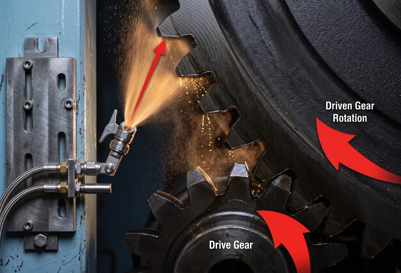
Open gear spray nozzles are almost always external mix. Nothing else copes reliably with a 15,000 cSt lubricant carrying graphite. This is the single most important design decision in the nozzle. The air cap in the figure above is external mix: the fluid orifice sits at the centre, between two air horns.
What the air cap does
The air cap does two jobs at once. It shears the fluid stream into droplets, and it shapes the emerging pattern.
Pattern types include flat fan, full cone and hollow cone. Flat fan is standard on spray bars. The target is rectangular — tooth height by face width — so a fan maps to it properly.
Higher-specification nozzles split the air into two independent feeds. One controls droplet size, the other controls fan geometry. That decouples atomisation quality from coverage area, which is useful in cold or variable conditions.
04Air pressure
A narrow window.
Air pressure sets droplet size. Miss the window in either direction and the film fails.
Too low
Break-up is incomplete. Lubricant lands lumpy, stringy or splattered. Coverage develops gaps, and those gaps become scuffed bands on the flank.
Too high
The jet over-penetrates. Lubricant is blown off the tooth rather than deposited on it. Fine fog drifts, coats the guard interior and is wasted. Transfer efficiency collapses.
| Setting | Range |
|---|---|
| Manifold air supply | 5.5–8 bar (80–120 psi) |
| Nozzle setting | roughly 5–6 bar (75–90 psi) |
Always confirm against the system OEM and the lubricant supplier. The correct window shifts with lubricant viscosity, ambient temperature and standoff distance.
Cold weather narrows the window sharply. Viscosity climbs and atomisation degrades. Some systems fit electric heaters at each nozzle for this reason.
05Geometry
Where the spray has to land.
This is where most installations go wrong. Perfect nozzle internals do not help if the fan is aimed badly.
The target is the loaded flank of the girth gear teeth, over full tooth height and full face width.
AGMA guidance directs the spray at the gear, not the pinion. The pinion is fed by transfer through the mesh. It passes through contact many times per gear revolution, so it picks up film continuously. The figure above shows exactly that: the fan is aimed at the driven gear, before the mesh.
| Parameter | Guideline |
|---|---|
| Number of nozzles | Set by face width. Four to six is typical. |
| End nozzles | 50–65 mm in from the gear face edge |
| Intermediate nozzles | Roughly 130–180 mm centres |
| Standoff | About 200 mm from the tooth, ±50 mm |
| Spray bar angle | About 30° to the flank |
| Position around the gear | Any of four positions relative to rotation, provided lubricant is applied before the mesh |
A 30° attack throws lubricant along the working profile, up or down, rather than square at the tooth tip. It distributes the film over the load-carrying flank instead of piling it on the addendum. Trim the standoff to suit air pressure and tooth height.
Adjacent fans must overlap. There must be no dry stripes anywhere across the face. Gaps are the failure mechanism, not a cosmetic issue.
06Dose and timing
Short and frequent beats long and heavy.
Dose is expressed in grams per centimetre of face width per hour. The lubricant supplier sets the starting rate.
ANSI/AGMA 9005 provides fall-back quantity guidelines where a supplier rate is not available.
Spray duration should equal one full gear revolution, and preferably two. That guarantees the entire circumference is covered in a single cycle. Two hours is the maximum permitted between applications under AGMA guidance.
| Product type | Interval |
|---|---|
| Residual and high-viscosity synthetic | 10–20 minutes |
| Semi-fluid grease, gel and polymer-thickened | 15–30 minutes |
Diluent-containing products need short intervals. The diluent evaporates after landing and the film thins. Wait too long and flank protection is lost before the next dose arrives.
Injector drift
Injector output falls with wear. Weigh the discharge per cycle periodically and compare it against the rated output. Never assume a metering device is still delivering its nameplate volume.
07Verification
Never assume. Check.
Three checks. Each takes minutes, and each catches a different failure.
Pattern check
With the machine isolated and locked out:
- 01Open the inspection door.
- 02Tape clean card across the gear face at the spray target.
- 03Run one lubrication cycle.
- 04Read the deposit.
Look for continuous overlapping coverage over full tooth height and full face width. Ragged edges, blobs or dry stripes mean the air pressure, spray angle or air cap needs adjustment. Repeat until the pattern is clean.
Specify a spray bar that swings out. A bar that cannot be inspected safely will not be inspected.
Strobe check, running
Set the strobe to gear speed. A properly lubricated gear appears dark to semi-transparent, depending on product type. Strings of lubricant should be visible as gear and pinion teeth separate. Heavy black build-up, dripping and filled roots indicate over-application.
Thermal check
Traverse the gear face with a non-contact thermometer. Even temperature across the face indicates even lubrication. A gradient of roughly 15 °C across the face points to misalignment or a coverage gap.
Strobe appearance and thermal traverse together make a fast, cheap alignment screen.
08Failure modes
Most gear problems are application problems.
Five failures trace back to the nozzle. Each presents as something else.
- Blocked or partly blocked nozzle. A dry band on the flank. Localised scuffing, micropitting and a developing wear step. Usually traced to an inadequate air purge, or to diluent drying in the tip.
- Under-application. Thin film, boundary contact, rising pinion temperature and accelerated wear.
- Over-application. Root filling, added parasitic drag, lubricant slung off the gear, a contaminated guard and poor housekeeping. Lubricant sitting in the root carries no load.
- Wrong target. Spraying the unloaded flank, or spraying only the pinion. The film never reaches the working contact properly.
- Excess fogging. Almost always air pressure set too high. Waste, plus a dust-collecting coating on the guard interior.
09Airless systems
The alternative.
Airless systems remove compressed air from the equation.
A pressurised accumulator drives a measuring piston, which forces lubricant through a spray valve and nozzle at high hydraulic pressure.
The advantages are less plumbing, no compressed air, and no atomised fog. Transfer efficiency is higher, and stiffer products spray, up to NLGI 2.
The trade-offs are coarser droplets and less flexible pattern control. Valve and tip components run at higher pressure, and need maintaining.
Air-assisted remains the more common choice on mill and kiln girth gears. Airless is attractive where compressed air is scarce, or where fog contamination is unacceptable.
10Checklist
What to confirm on site.
- Confirm the nozzle is external mix, and rated for the lubricant's viscosity and solids content.
- Set nozzle air pressure inside the supplier's window. Verify with a gauge at the manifold, not at the compressor.
- Check the purge delay clears the tip fully every cycle.
- Match nozzle count to face width. Four to six is typical.
- Set end nozzles 50–65 mm in from the face edge, and intermediates at 130–180 mm centres.
- Set standoff near 200 mm.
- Set the bar near 30° to the loaded flank.
- Aim at the girth gear, before the mesh.
- Card-test the pattern. Confirm overlap, and no gaps.
- Set spray duration to one gear revolution, preferably two.
- Keep the interval short. Never exceed two hours.
- Weigh injector output against its rated output at scheduled intervals.
- Strobe the gear and traverse the face with an infrared thermometer as routine condition monitoring.
- Specify a swing-out spray bar on any new installation.
11Basis & further reading
This article draws on ANSI/AGMA 9005-F16 Industrial Gear Lubrication (previously 9005-E02 and 9005-D94), ANSI/AGMA 6014-B15, ISO 18792:2008, and published open gear application guidance from lubricant and lubrication-system suppliers.
Always confirm application rates, intervals and pressures against the gear OEM's instructions and the lubricant supplier's product data. The figures given here are general industry guidelines, not a substitute for equipment-specific recommendations.